THE CYLINDRICAL COORDINATE SYSTEM
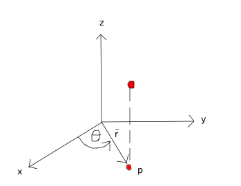
A cylindrical coordinate system is a mix between the three-dimensional Cartesian and the polar coordinate systems. This coordinate system is allows one to express various surfaces in a more simplified manner than the Cartesian coordinate system. It is especially useful for problems involving symmetry about an axis, such as the flow around a helicopter rotor, propeller, or wind turbine. The two-dimensional polar coordinate system is extruded along a third axis, resulting in a long cylindrical shape, as illustrated in Fig. 2↑. When analyzing a cylindrical coordinate system, the positions involving the x and y axes in Fig. 2↑ are evaluated using the polar coordinate transformation, while the z axis provides the “height”. For example, point P in three-dimensional space is represented by the coordinate system (r, θ, z), where er and eθ are the unit polar coordinates of the projection of P onto the x − y plane, while z is the vertical distance to P in Fig. ↓.
POLAR COORDINATES
Polar coordinates allow motion to be defined as a radius and angle with respect to an origin, rather than the conventional distances (x, y) found in the Cartesian coordinate system. The unit vectors of the polar coordinate system are the radial distance from the origin, r and the angle from a specified 0○ line (here, the x axis), eθ, illustrated in Fig. 2↑.
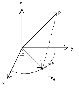
It is necessary to change coordinate systems or frames of reference between the Cartesian and cylindrical coordinate systems. There is a simple frame transformation between these two coordinate systems. Using Fig. 2↑ to define the two frames of reference, the transformation is observed to be
y = rsinθ
x = rcosθ
z = z
Notice that the z − axis remains the same for both the polar and Cartesian coordinate systems.
Other important relationships between the cylindrical and Cartesian reference frames include:
r = √(x2 + y2)
θ = tan − 1((y)/(x))
The relation between the unit vectors can be found by using the transformations above along with the dot product:
(1)
i
=
cos(θ)er − sin(θ)eθ
j
=
sin(θ)er + cos(θ)eθ
k
=
k
or, the inverse
(2)
er
=
(x)/(r)i + (y)/(r)j
eθ
=
− (y)/(r)i + (x)/(r)j
k
=
k
The derivatives with respect to each coordinate axis must be taken with care, as the transformation generates an extra term. Consider the derivatives of a scalar, A = A(x, y, z), which yield < (∂A)/(∂r), (1)/(r)(∂A)/(∂θ), (∂A)/(∂z) > . There is an additional 1 ⁄ r term in the eθ derivative which must be included.
Additional vector operations with the cylindrical coordinate system are provided in cross products.