 |
||||||||
 |
 |
 |
 |
|||||
 |
||||||||
 |
||||||||
 |
 |
|||||||
 |
||||||||
 |
||||||||
 |
||||||||
 |
||||||||
 |
||||||||
FREE BODY DIAGRAMS
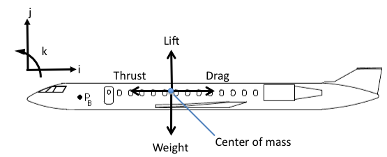
The free body diagram (FBD) is arguably the most important concept to master in engineering. The free body diagram is a simple representation used to show the relative magnitude and direction of all forces and moments acting upon an object in a given situation, and it should act as a template for correctly writing and applying the equations of motions in solving the problem. Free body diagrams isolate each body in a system from all other interacting bodies, utilizing Newton’s laws of motion. The size of the vectors in a free-body diagram is sometimes, but not usually, reflective of the magnitude of the force and moment. The direction of the vector reveals the direction of and location upon which the force or moment is acting. It is important to understand the context of the problem when sketching a free body diagram; a FBD for an aircraft in static equilibrium (flying straight and level) will have a different FBD than an aircraft flying a maneuver. An example of a free body diagram is shown in Fig. 1↓.
BASIC COMPONENTS OF A FREE BODY DIAGRAM
Every free body diagram should include several basic components no matter the coordinate system or its classification as static or dynamic.
- Define and identify the coordinate system: sketch the unit vectors, indicating the direction of the positive orientation. Include the positive direction of moments, if applicable, using the right hand rule.
- Sketch vectors that describe the anticipated motion, including both translation and rotation. The direction is the “best guess”, but if it is incorrect, the magnitude will be negative, indicating the direction is in the opposite direction.
- Draw all external contacts, constraints, and body forces and moments: These may include forces such as friction, gravity, normal force, drag, tension, or a human force due to pushing or pulling.
Problem strategy is also an important concept to master when generating a FBD. Though it does not guarantee one will be able to solve the problem correctly, it is a necessary step. A body in equilibrium may well have a different FBD than the same body undergoing dynamic motion. Below are several steps that should be followed before drawing a free body diagram:
- Read the problem and determine whether it is a static (equilibrium) or dynamic (non-equilibrium) problem. Note the direction and behavior of any expected motion (though it is usually not drawn as part of the FBD).
- Identify the most appropriate coordinate system, sketch the axes, and identify the origin.
- Carefully determine all of the external forces that are acting upon each object of interest (there may be more than one).
- Determine the expected direction and magnitude of each force and moment, as well as the location of their application
- Go back and make sure everything was accounted for
From this diagram, the equations of motions should be able to be written. Using Newton’s laws, the equations of motion should add up to zero in each direction for a body in equilibrium, but they will not be zero in the direction of the motion.
Next Page →
Next Page →