 |
||||||||
 |
 |
 |
 |
|||||
 |
||||||||
 |
||||||||
 |
 |
|||||||
 |
||||||||
 |
||||||||
 |
||||||||
 |
||||||||
 |
||||||||
In this calculation, since the velocity of point C will be normal to the vector rAC, the vector VC can be replaced by VC m/s i. The sign of magnitude will be computed automatically from the calculation, though it can inferred from the problem sketch. This is also a good check to make sure that the calculation is done properly.
The calculation of the velocity of point C was computed using point A, but it can also be computed using point B. The two values for VC should be identical if the computations have been performed correctly.
VC
=
VB + ω × rBC
VC m/s i
=
− 3 m/si + ( − 5 ⁄ 4) rad/s k × 1 m j
VC m/s i
=
(12 − 5)/(4) m/s i
VC
=
− (7)/(4) m/s
So point C moves with a magnitude of 7/4 m/s in the negative i direction, or to the left (7/4 m/s ← ).
Example 2: Multiple Bodies in Rotation
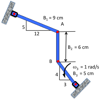
A more complex example is shown here, where the bars move in multiple directions. While simple bars, this example can illustrate the motion of a crane in space or the action of a landing gear extension mechanism. The motion is restricted to planar motion to illustrate the concepts without overly complicating the mathematics.
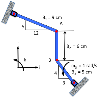
The multiple bar configuration is shown in Fig. 3↓. Again, the first step is to identify the coordinate system; here again the Cartesian coordinate system will be a good selection, as illustrated in Fig. 4↓.
Bars one and three do not fall along an axis as in the prior example. It is important to extract as much information as possible from the instantaneous position of the system. Looking first at bar three, some insights into the velocity at point B can be made. First, the velocity will be normal to the position vector that starts at the pivot at the wall to point B. Given the angular velocity in the counterclockwise position, the direction of the velocity at point B can be extracted, as seen in Fig. 5↓.
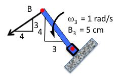
The orientation of bar three is given by the 3-4 labeled triangle adjacent to the bar. Thus, when the triangle is rotated by 90○, it indicates the velocity of point B. The length of the bar is 5 cm, so the triangle showing the bar position also gives the length in each of the coordinate axes (i.e., 3 i cm and 4 j cm) since the hypotenuse of the 3-4 cm triangle is 5 cm.
Next Page →
Next Page →
← Previous Page
← Previous Page